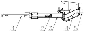
The operation of the concrete pump encompasses the use of hydraulic and electrical systems. The concrete pump is designed to safely pump wet concrete through a delivery system of pipes and hoses within its published ratings and specifications.

Stability of the concrete pump during operation is provided by the outriggers and front jack. Controls for the outriggers are located on the sides of the concrete pump.
The pumping system employs a S-Tube design valve system. This system incorporates material cylinders linked to hydraulic cylinders that cycle alternately. With concrete material in the hopper and the pump operating, a material cylinder retracts, drawing material into the cylinder. At full retraction of the cylinder, a signal is sent to both the S-tube swing cylinder and the drive cylinder directional valves causing the s-tube to shift position to the fully loaded material cylinder and the drive cylinders to change direction. The concrete piston of the loaded cylinder then pushes the material through the s-tube and into the delivery lines. The shifting from one cylinder to the other cylinder takes place providing a continuous flow of material through the delivery piping system. The pump can be operated at the control panel or can be operated from the remote control.
The hydraulic oil flow created by the hydraulic pump pushes the drive cylinder pistons inside the drive cylinders
(1) alternately back and forth. Because the drive cylinders and concrete pistons
(2) inside the concrete cylinders
(3) are linked together, the pistons move synchronously.
When a drive cylinder retracts along with the concrete piston, concrete will be sucked from the hopper into the concrete cylinder. Simultaneously, the other drive cylinder and concrete piston are extended toward the hopper. The concrete piston will push concrete from the concrete cylinders through the S-Tube
(4) and out to delivery system
(5)Next, the pump switches at the end of the stroke, causing the s-tube valve to shift to the other concrete cylinder which has sucked and filled the cylinder with concrete, starting the next cycle.
Reverse pumping links the concrete piston in the suction stroke and S-Tube valve to suck concrete from the s-tube instead of the hopper. As a result, the concrete piston pumps concrete into the hopper.
The power for operation of the concrete pump is provided by the engine, which drives the hydraulic pumps.
All functions for operation of the concrete pump can be accomplished from the local controls mounted on the side of the unit. Optional hand-held cable or radio remotes enable the pump to be operated away from a remote distance.